CATEGORY: SLIDE-OUTS & COMPONENTS
TOPIC: FULL-WALL SLIDE FIX
Posted: 11-25-15 thru 4-23-18
Posted By: falconhunter, retiredfields, subframe, and several others
See Forum Post HERE
We have been having trouble with our full slide going out and being underpowered or not powering the motor at all. After Our dealer made a few calls to Lifestyle, it turns out that this is somewhat common. The wire going from the battery, fuse box, in and out switch, then the safety switch (where the door to the bedroom latches) then on to the motor is just too long for the wire size. The motor has a 22amp start surge then runs at 12 amps. The fix is going to be a relay with #8 wire. using the current wire for tripping the relay. Will let you know how it’s goes after the repair.
My full slide also failed. It was getting sluggish, then stuck, now it won’t move at all. I assume it’s the same problem. Can you guys post a good set of instructions and list of parts all in one place? Then we can share step by step instructions with repair center. Thanks!
The installation is fairly simple.
1) Buy this or something similar http://www.amazon.com/Reversing-Continu … ge_o09_s00
2) Buy this or something similar http://www.amazon.com/Blue-Sea-Systems- … ge_o04_s00
3) Visit this page for the wiring diagram http://www.texasindustrialelectric.com/relays_24450.asp
4) Run a #8 wire from the +12v battery, through an automotive circuit breaker, through the battery disconnect switch, to the area of the slideout motor.
5) Run a #8 wire from the -12v battery directly to the slideout motor area.
6) Mount the solenoid in the motor area.
7) Cut the motor wires, add connectors, and attach them to the solenoid per the wiring diagram
8) Connect the battery wires to the solenoid per the wiring diagram.
You should be good at this point. If the switch is reversed just swap the two switch wires on the solenoid.
Again, I suggest installing and using the battery disconnect switch to prevent any surprise slideout movement while driving or parked. Turn it on to move the slides, then turn it off.
Just curious why you used such a large circuit breaker? 40 amps seem too much for safe protection for the motor. The leads on the motor are only 14 gauge. If there was a problem it could cause a meltdown of the wires before the breaker trips. My motors are protected by 15 amp fuses from the factory and even with the small wire size, they have never tripped. It’s not safe to overprotect a circuit.
As an electrician, I agree with Chip…..The motor will burn out before the 40 amp breaker will trip… The #8 wire size is to keep the voltage up because of the distance..
Good setup on the fuses. I used #8 speaker wire. It is like welding wire, extremely flexible and easy to get around corners. This wire is used for heavy duty automotive sound systems.
http://www.ebay.com/itm/271178621071?_t … EBIDX%3AIT
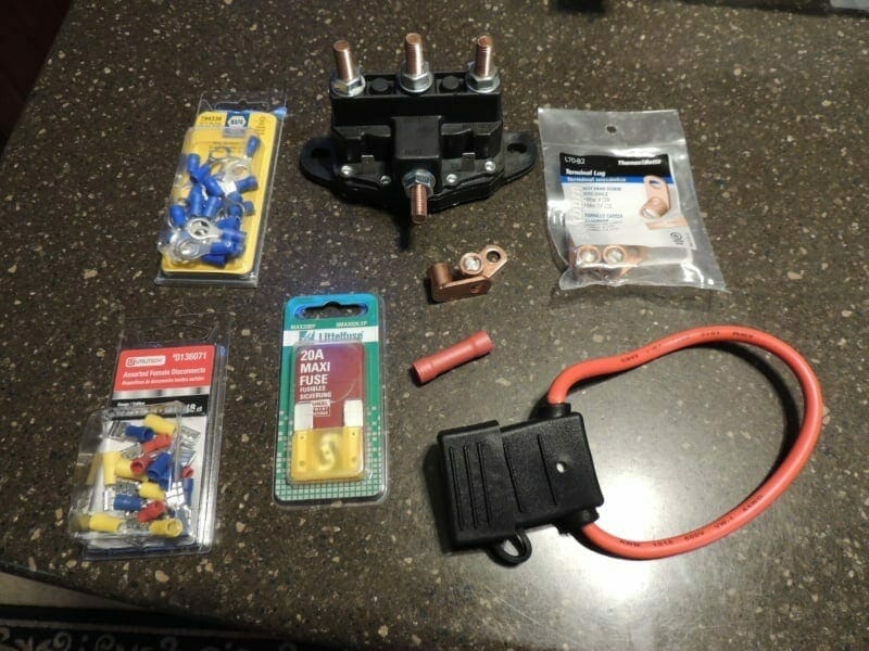
After reading subframe’s post I changed my plan of attack. I purchased everything I needed today. I decided to go with a Maxi fuse off of the battery instead a self resetting breaker for safety reasons. Based on voltage drops using this calculator,
http://www.calculator.net/voltage-drop- … &x=66&y=11
I would use 10 AWG wire instead of the 8 AWG simply because you can purchase everything you need at a local NAPA dealer except for the solenoid and the voltage drop is not that different. I had a hard time finding connectors for the #8 wire here where I’m at but #10 was everywhere. The #8 wire has a 1.8% drop, the #10 has a 2.8% drop and the factory setup has roughly a 13% +/- drop in voltage.
I have 63.00 invested for everything including:
1) $13.00 30′ of wire from Lowes, 15′ red and 15′ black
2) $6.00 terminal lugs from Lowes
3) $14.00 Fuse holder from napa
4) $4.00 Fuse from Napa
5) $5.00 Misc connectors
6) $21.00 solenoid from Amizon
I sure hope this speeds up the FWS and helps the longevity of the motor. The only thing I don’t like about my setup is the only in-line fuse holder with a #8 wire I could find is a Maxi fuse and the smallest fuse available for it is 20 amps. Also, trying to find connectors for 5/16″ posts is a little problematic. I found some for the #14 wire at Napa but for the #8 wire lugs I have to drill out the 1/4″ to 5/16″, not a big deal as the lugs I bought are plenty beefy.