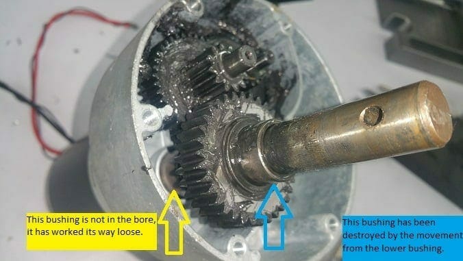

This is a work-in-progress and has to do with FalconHunter’s thread “slide out motor bolts and shaft support fix” but I thought I’d document this in a new thread to keep down the clutter on that one.
Besides, this type of fix should be done to all motors of this type as a preventive measure. I will add PDF files with detailed drawings as time allows.
While I was installing my Slide Motor Supports, I noticed that the Slide Motor shaft had way too much play in it, causing chatter even when the slide support was installed. I took the motor apart and it is a design flaw that causes the lower bushing to work its way loose, then slide up the shaft. Once it’s no longer in the bore, the shaft is free to slop around and cause all sorts of problems, including elongating the top bushing bore by .025″ (on mine)
The fix will be to re-bore the cap for the top bushing, make a new
Click on any Image to open in Lightbox View
It also elongated the top bushing bore in the Motor Cap by ~.025″
“Alloy” Quote: I found the same poor fit up with the inside bushing on ours. I sanded everything and used lots of Loctite Red to hold the bushing in. FYI…..first time I put the gearbox back together it locked up after turning the motor by hand. After pulling it apart 2 more times it worked but I never figured out why it locked up. When I took the 2nd gearbox apart I marked the gears. It went back together without any issues.
First gearbox rebuild is done and under test today. I bench tested it in forward and reverse for several minutes and it runs smooth and quiet. First was a measurement of the cap to make a CAD file so you know exactly where the bores are. This information is used to align the cap before machining.
- Zeiss CMM to reverse engineer the bore locations.
Then put on Mill to bore. This could also have been done on a manual mill with a boring head. I had to open up the .7900″ bore to .8300″ to clean it up 100%
- CNC Mill to cut new bore
[TIP: WD40 in a gallon can make for a great solvent to remove that black lithium grease. Acetone or Alcohol does nothing to it. Make sure you re-apply grease during re-assembly]
[TIP: NEVER use Acetone on Oilite bushings, it will remove the impregnated oil.]
For the top, I used a McMaster 2938T46 bushing and machined the O.D. to .8298″ to leave a little room for Loctite 603. The bushing is captured between the top cap bore and the 5/8″ final gear when installed.
Uncut 2938T46 on Left, original on Right
- McMaster 2938T46
Cut 2938T46 on Left, original on Right
- Machined 2938T46
For the bottom, I chose to use a longer bushing to trap it between the gear housing and the intermediate gear.
I turned the O.D. to .7900″ for .47″ deep since the bore for the original bushing was not oblong.
A snap ring on the final shaft holds this in place, along with Loctite 603. No matter what, this is not going to come loose.
Left is stock 2938T49, mid is original, right is modified 2938T49
- McMaster 2938T49
The cap and housing were engineered wrong, but there is little that can be done except something like this or to make new ones using the correct design.
The bearing bores should have been made with room to install internal snap rings to hold the bushings in-place statically, not with a dynamic rotating device like I had to use, but there is no material on the castings to do it that way.
Some of my pictures didn’t take, so I will update this post with a few more detailed shots when I do the other side.
I’ll also include a PDF of the cap to show the correct location of the bores relative to each other. Since one of the bores was oblong from the failure, I verified the distances/angles using the gears in-mesh with zero preload.
This will yield a motor that is so strong, you will need to read Alloy’s post about adding in slide stop limit switches.
I cannot believe they expected people to just run the motor until it hits a hard stop and overloads.
Update: July 4th I installed the rebuilt Motor/Gearbox and “The Fix” brackets.
The slide glides in and out smoothly, no sticking, no shaking.
Perfect!